
Connector map
There are 13 connectors on the board: 7 on the top side and 6 on the bottom side. They sit along the two long edges and face outwards. This guide numbers them J1 to J13 in order, starting at the USB-C end, and gives each one a name.
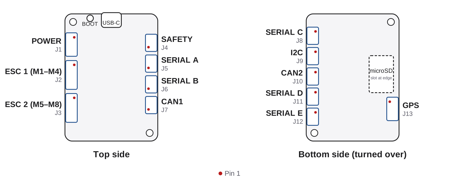
| No. | Port | Side | Pins | Use |
|---|---|---|---|---|
| J1 | POWER | Top | 6 | Battery input, 5S–12S |
| J2 | ESC 1 | Top | 8 | Motor outputs 1–4, ESC telemetry, current, battery |
| J3 | ESC 2 | Top | 8 | Motor outputs 5–8, ESC telemetry, current, battery |
| J4 | SAFETY | Top | 4 | Safety switch and its LED |
| J5 | SERIAL A | Top | 4 | Serial port |
| J6 | SERIAL B | Top | 4 | Serial port |
| J7 | CAN1 | Top | 4 | CAN FD bus 1 |
| J8 | SERIAL C | Bottom | 4 | Serial port |
| J9 | I2C | Bottom | 4 | Second I2C bus |
| J10 | CAN2 | Bottom | 4 | CAN FD bus 2 |
| J11 | SERIAL D | Bottom | 4 | Serial port |
| J12 | SERIAL E | Bottom | 4 | Serial port |
| J13 | GPS | Bottom | 6 | GPS and compass |
Signal lines are 3.3 V logic. In the tables, TX is an output from the flight controller and RX is an input to it. Connect the TX of a device to the RX of the port, and the RX of the device to the TX of the port.
POWER (J1)
| Pin | Signal | Notes |
|---|---|---|
| 1 | VBAT | Battery positive, 5S–12S (18–52 V) |
| 2 | VBAT | Battery positive |
| 3 | VBAT | Battery positive |
| 4 | GND | |
| 5 | GND | |
| 6 | GND |
Warning
This port takes the full battery voltage. Check the polarity of your cable before you connect a battery. A Pixhawk power module cable carries 5 V and sensor lines on these pins, not battery voltage, and must not be used here.
ESC 1 (J2) and ESC 2 (J3)
Each ESC port carries four motor outputs, so two 4-in-1 ESCs give eight motors. Each port also brings battery power, a current signal and ESC telemetry back from the ESC. All eight motor outputs support bidirectional DShot, so ArduPilot can read motor speed for the notch filter.
| Pin | ESC 1 (J2) | ESC 2 (J3) | Notes |
|---|---|---|---|
| 1 | GND | GND | |
| 2 | M1 | M5 | Motor output, PWM or DShot |
| 3 | M2 | M6 | Motor output |
| 4 | M3 | M7 | Motor output |
| 5 | M4 | M8 | Motor output |
| 6 | ESC telemetry (RX) | ESC telemetry (RX) | Both ports share one serial input, SERIAL7 |
| 7 | Current 1 | Current 2 | Analog current signal from the ESC |
| 8 | VBAT | VBAT | Battery positive from the ESC lead, 5S–12S |
Pin 6 on both ports goes to the same serial input. This works for ESCs that send telemetry one at a time when the flight controller asks, as AM32 and BLHeli_32 ESCs do with DShot telemetry requests.
SAFETY (J4)
| Pin | Signal | Notes |
|---|---|---|
| 1 | 3.3V | Supply for the switch and LED |
| 2 | Safety switch | Input |
| 3 | Safety LED + | LED anode |
| 4 | GND | LED cathode and ground |
A safety switch is optional. Most users turn it off: set BRD_SAFETY_DEFLT to 0 and the board does not wait for the switch before arming.
To fit one, use any momentary push button and any LED. Wire the button between pin 1 (3.3 V) and pin 2: pressing it pulls pin 2 high. Wire the LED from pin 3 (LED +, anode) to pin 4 (GND, cathode). The board already has the series resistor for the LED.
Arming tones and status lights
There is no buzzer pin and no status LED on the board. We suggest you follow the status through telemetry: the ground station shows the arming state, the flight mode and every warning, and Mission Planner can also read them out loud.
Serial ports
The five serial ports, SERIAL A to SERIAL E, use the same 4-pin order. They have no flow control (CTS/RTS) lines.
| Pin | Signal | Notes |
|---|---|---|
| 1 | 5V | Peripheral 5 V, 0.75 A PTC |
| 2 | TX | Output from the flight controller |
| 3 | RX | Input to the flight controller |
| 4 | GND |
| Port | No. | ArduPilot | Pixhawk role | Processor UART |
|---|---|---|---|---|
| SERIAL A | J5 | SERIAL1 | TELEM1: telemetry radio | USART1 |
| SERIAL B | J6 | SERIAL2 | TELEM2: companion computer | USART2 |
| GPS | J13 | SERIAL3 | GPS1 | USART3 |
| SERIAL C | J8 | SERIAL4 | GPS2: second GPS | UART8 |
| SERIAL D | J11 | SERIAL5 | TELEM3 | UART7 |
| SERIAL E | J12 | SERIAL6 | Free | USART6 |
| ESC telemetry | J2 and J3, pin 6 | SERIAL7 | ESC telemetry | UART4, RX only |
The numbers follow the Pixhawk order: SERIAL1 and SERIAL2 for telemetry, SERIAL3 and SERIAL4 for GPS. To use ESC telemetry, set SERIAL7_PROTOCOL to 16 (ESC Telemetry). To use a port for something else, change its SERIALn_PROTOCOL and SERIALn_BAUD. See Serial port configuration in the ArduPilot documentation.
Note
Pixhawk telemetry radios often come with a 6-pin TELEM cable. These ports are 4-pin, so use a 4-pin cable: 5V, TX, RX and GND. The two flow control wires are not needed.
RC receiver
There is no separate RC input. Connect the receiver to any free serial port, for example SERIAL E (SERIAL6). In ArduPilot, set that port's SERIALn_PROTOCOL to 23 (RCIN). See RC input in the ArduPilot documentation.
CAN1 (J7) and CAN2 (J10)
Both CAN ports use the 4-pin Pixhawk CAN order, so DroneCAN GPS units, compasses and other CAN devices made for Pixhawk plug straight in.
| Pin | Signal | Notes |
|---|---|---|
| 1 | 5V | Peripheral 5 V |
| 2 | CAN_H | |
| 3 | CAN_L | |
| 4 | GND |
Wiring the CAN buses
Each CAN bus has a 120 Ω termination resistor on the board. A CAN bus needs exactly two terminators, one at each end, so fit the second one at the far end of the bus and do not add another at the flight controller end. See CAN bus setup in the ArduPilot documentation for the DroneCAN side.
I2C (J9)
| Pin | Signal | Notes |
|---|---|---|
| 1 | 5V | Peripheral 5 V, 0.75 A PTC |
| 2 | SCL | I2C2 clock |
| 3 | SDA | I2C2 data |
| 4 | GND |
GPS (J13)
The GPS port uses the common 6-pin Pixhawk GPS order, so most GPS and compass modules made for Pixhawk plug straight in.
| Pin | Signal | Notes |
|---|---|---|
| 1 | 5V | Peripheral 5 V, 0.75 A PTC |
| 2 | TX | SERIAL3 (USART3) TX |
| 3 | RX | SERIAL3 (USART3) RX |
| 4 | SCL | I2C1 clock, for the compass |
| 5 | SDA | I2C1 data, for the compass |
| 6 | GND |
USB-C, BOOT button and microSD
USB-C is on the short edge, next to the BOOT button. The microSD slot is on the bottom side and opens on the same long edge as the GPS port. Use the BOOT button only to recover the board after a failed firmware update (see Firmware and updates).